Kia Cee'd: Troubleshooting / Compressor Repair procedures
Kia Cee'd JD Service Manual / Heating,Ventilation, Air Conditioning / Troubleshooting / Compressor Repair procedures
| Removal |
| 1. |
If the compressor is marginally operable, run the engine at idle speed,
and let the air conditioning work for a few minutes, then shut the engine
off.
|
| 2. |
Disconnect the negative cable from the battery.
|
| 3. |
Recover the refrigerant with a recovery/charging station.
|
| 4. |
Remove the right side front tire.
|
| 5. |
Separate the front portion of the front wheel guard from the wheel house.
|
| 6. |
Remove the rear part of the front side engine room under cover (A).
|

| 7. |
Loosen the drive belt.
(Refer to Engine Mechanical - "Drive Belt")
|
| 8. |
Disconnect the suction line (A) and discharge line (B) from the compressor.
|


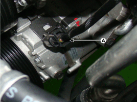
| 9. |
Disconnect the compressor switch connector (A).
|
| 10. |
Remove the compressor (A) by loosening the mounting bolts.
|

| Installation |
| 1. |
Make sure the compressor mounting bolt with the correct length is screwed
in. Tighten the mounting bolts with the specified tightening order.
|

| 2. |
Installation is the reverse order of removal.
|
| Inspection |
| 1. |
Check the plated parts of the disc & hub assembly (A) for color changes,
peeling or other damage. If there is damage, replace the clutch set.
|

| 2. |
Check the pulley (B) bearing play and drag by rotating the pulley by
hand. Replace the clutch set with a new one if it is noisy or has excessive
play/drag.
|
| 3. |
Check operation of the magnetic clutch.
Connect the compressor side terminals to the battery (+) terminal and
the ground battery (-) terminal to the compressor body. Check the magnetic
clutch operating noise to determine the condition.
|

| Disassembly |
| 1. |
Remove the right side front tire.
|
| 2. |
Separate the front portion of the front wheel guard from the wheel house.
|
| 3. |
Remove the rear part of the front side engine room under cover (A).
|
| 4. |
Loosen the drive belt.
(Refer to Engine Mechanical - "Drive Belt")
|
| 5. |
Remove the center bolt (A) and the hub bolts while holding the pulley
with a disc & hub assembly bolt remover (09977-3R000).
|

| 6. |
Loosen the mounting bolts and then remove the disc & hub assembly (A).
|

| 7. |
Remove the pulley (B) after removing the snap ring (A) with snap ring
pliers.
|

| 8. |
Reassembly is the reverse order of disassembly.
|
 Compressor Components and components location
Components
1. Center
Bolt
2. Hub Bolt
3. Hub Assembly
4. Snap Ring
5. Pulley
6. Compressor Assembly
7. Electric Control Valve
...
 Condenser Repair procedures
Inspection
1.
Check the condenser fins for clogging and damage. If clogged, clean
them with water, and blow them with compressed air. If bent, gently
bend th ...
Other information:
Kia Cee'd JD Owners Manual: Hitches
It's important to have the correct hitch
equipment. Crosswinds, large trucks
going by, and rough roads are a few reasons
why you’ll need the right hitch. Here
are some rules to follow:
Do you have to make any holes in the
body of your vehicle when you install a
trailer hitch? I ...
Kia Cee'd JD Service Manual: Troubleshooting
Troubleshooting
Symptom
Possible cause
Remedy
Tachometer does not operate
Memory2 fuse (10A) blown
Check for short and replace fuse
CAN line faulty
Check the EMS
...
© 2017-2025 www.kceed.com
